At a glance — the full journey
A borehole is a built structure underground: a drilled shaft, steel or PVC lining (casing), a gravel filter around the screen, cement seals, and finally test pumping to prove yield and water quality before your pump goes in.
Typical timeline
Survey and permits first, then 5–14 days on site depending on depth, geology, and weather.
Who comes to site
Rig operator, driller, engineer, and safety lead — coordinated by a site supervisor.
What we bring
Drilling rig, compressors, rods, casing, gravel, cement, water bowsers (if needed), and test-pump gear.
What you provide
Clear site access, survey point marked, landowner consent, and a safe working area away from buildings and power lines.
What you are actually building underground
A borehole is not just a hole — it is a engineered water structure. Understanding the parts helps you ask better questions when reviewing quotes and site reports.
- Surface seal Stops polluted runoff from entering the borehole.
- Plain casing Protects unstable upper soils; keeps bad water out.
- Screen + gravel Filters sand while letting groundwater in — critical for pump life.
- Development Cleans fines so flow and clarity improve before equipping.
Standard pilot hole before casing
Fits most submersible pumps
County and geology dependent
With proper development & maintenance
Before the rig arrives on your land
Good preparation prevents delays, protects neighbours’ wells, and keeps your project on programme.
- Hydrogeological survey doneDrilling coordinates are marked with GPS — we drill exactly on the survey point, not “near the house”.
- Permits in progress or completeWRA, NEMA, and county requirements vary by location; we advise on the full compliance package.
- Access for heavy trucksConfirm the rig path — bridges, gates, slopes, and turning room for a truck-mounted rig.
- Power and water planWe run on diesel generators; drilling water may be trucked in if there is no on-site source.
- Safety bufferKeep children, livestock, and vehicles outside the marked work zone during operations.
Request a written programme before mobilization: expected depth range, casing type (PVC or steel), estimated days on site, and what is included in your per-metre rate (gravel, test pumping, headworks).
Mobilization
Getting people, rig, and materials to your site
What you will see
- Trucks arriving with the rig, rods, casing, gravel, and support equipment
- Crew offloading and laying out the site compound
- Generators/compressors positioned and tested
Your role
- Ensure gate access and show the survey stake
- Introduce us to the landowner or caretaker
- Point out buried pipes, septic tanks, or power cables nearby
Mobilization is the transition from office planning to field execution. We verify GPS coordinates from your hydrogeological report, confirm rig access, and deliver everything needed for the full programme in one coordinated trip — especially important in distant counties where return journeys are costly.
Key activities include site planning, loading and transport of the rig and materials, deployment of drillers and engineers, and liaison with local authorities or neighbours so access stays smooth and disruption stays low.
- Site planningGPS check against the survey report and rig positioning plan.
- Equipment deliveryRig, compressors, rods, casing, gravel, safety gear, and water supply if required.
- Crew briefingRoles assigned — driller, rig operator, engineer, safety supervisor.
Client takeaway: Mobilization cost reflects distance and logistics — especially in northern and arid counties. It is a one-time project fee, separate from metres drilled.
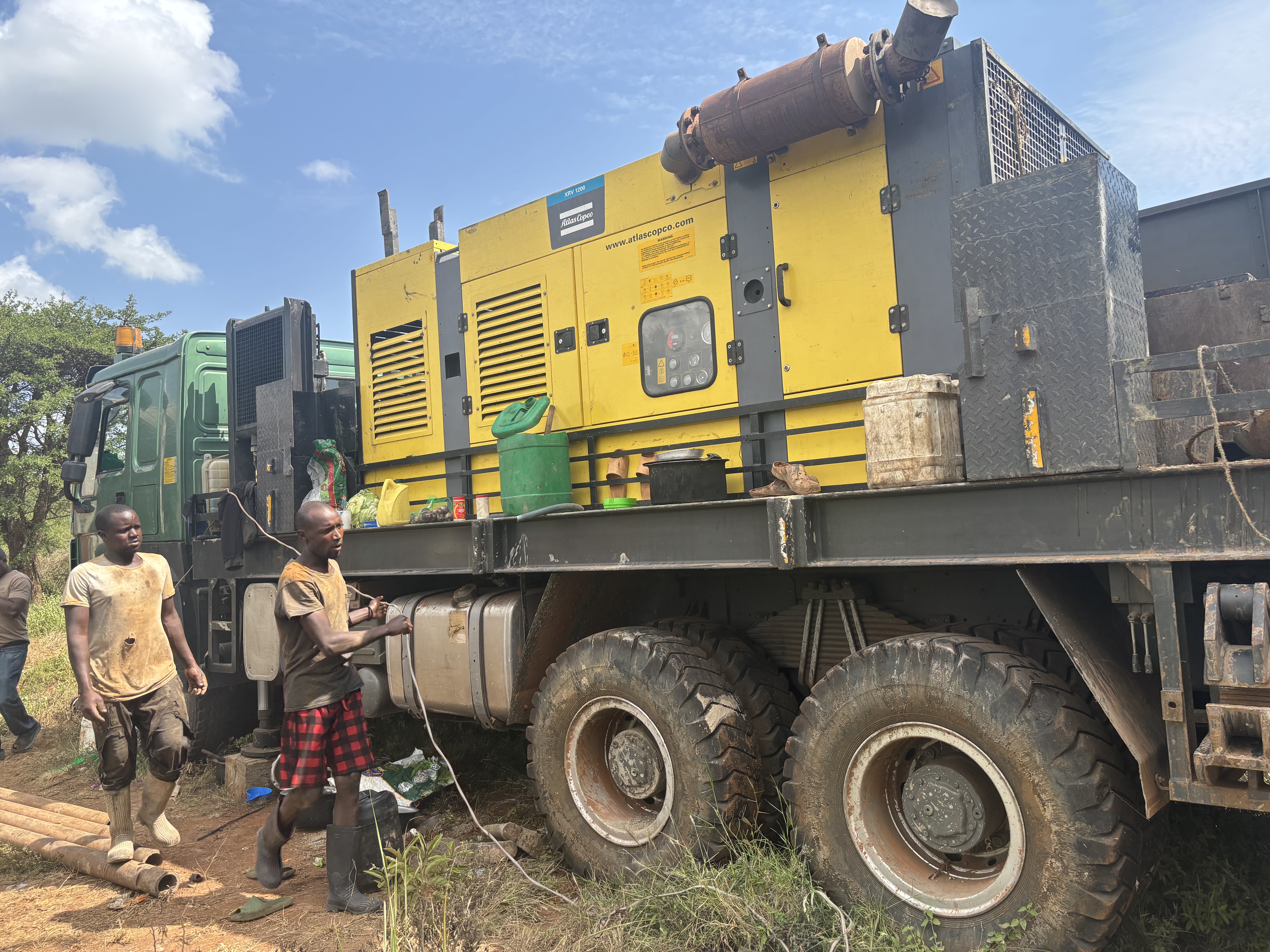
Watch: Mobilization in the field
Behind the scenes as our team moves the rig and stages materials for drilling.
Site setup
Safe, level, and ready to drill vertically
What you will see
- Rig mounted over the survey point and levelled with jacks
- Safety tape, signs, and cleared work zone
- Water tanks, compressor lines, and material staging areas
Your role
- Keep the marked zone clear of visitors during setup
- Confirm any underground services we should avoid
- Provide contact for emergencies (local chief, security, etc.)
Site setup creates a controlled workspace: the rig is aligned vertically over the borehole point, hazards are marked, and water plus power systems are tested before the first metre is drilled. A straight borehole protects casing, pump life, and long-term yield.
We clear vegetation, establish tool stations for rods and casing, run a team safety briefing, and adapt to terrain — rocky highlands, black cotton soil, or sandy coastal zones each need slightly different setup discipline.
Client takeaway: A rig that is not plumb (vertical) can cause casing wear, pump strain, and costly rework. Setup quality is visible — ask to see alignment checks.
Watch: Site setup
Clearing, levelling, and positioning the rig for safe drilling operations.
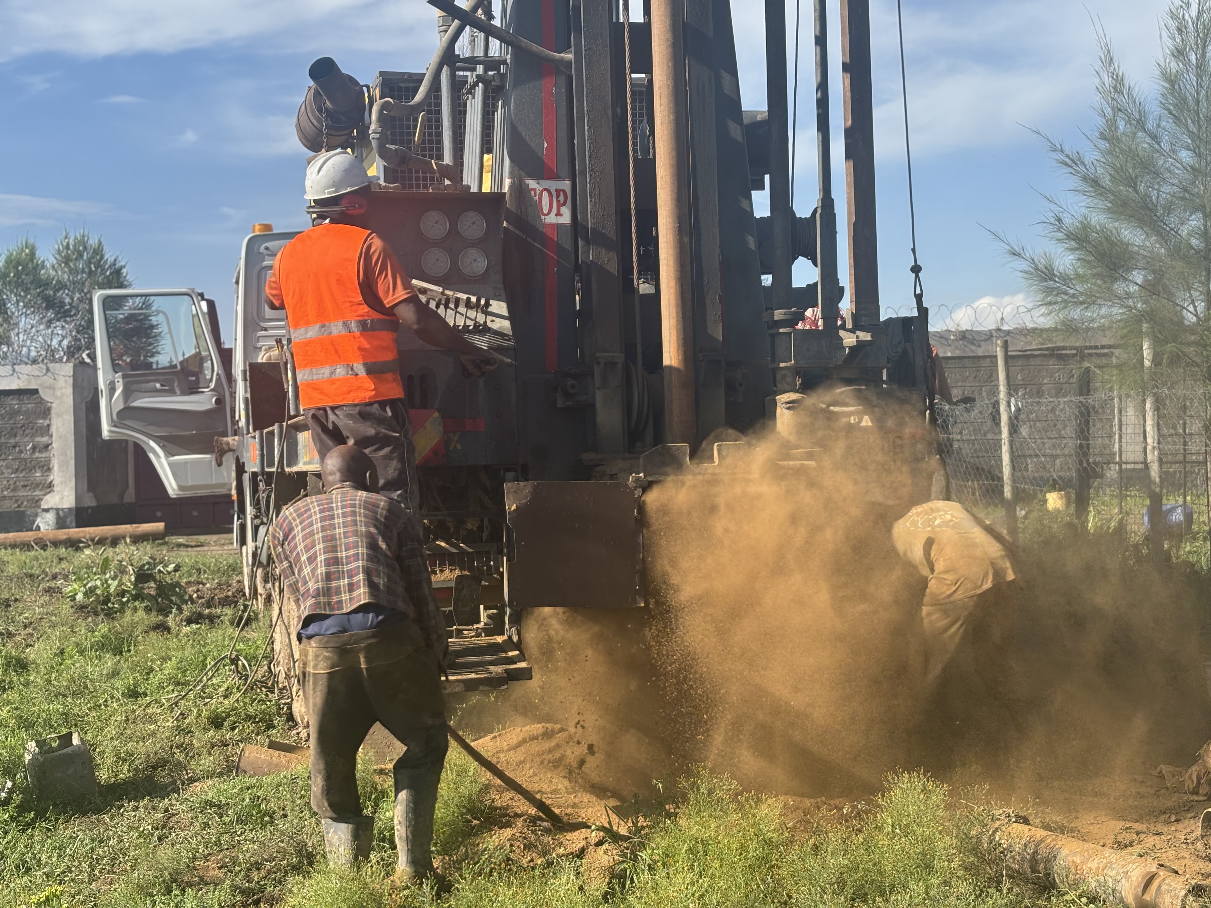
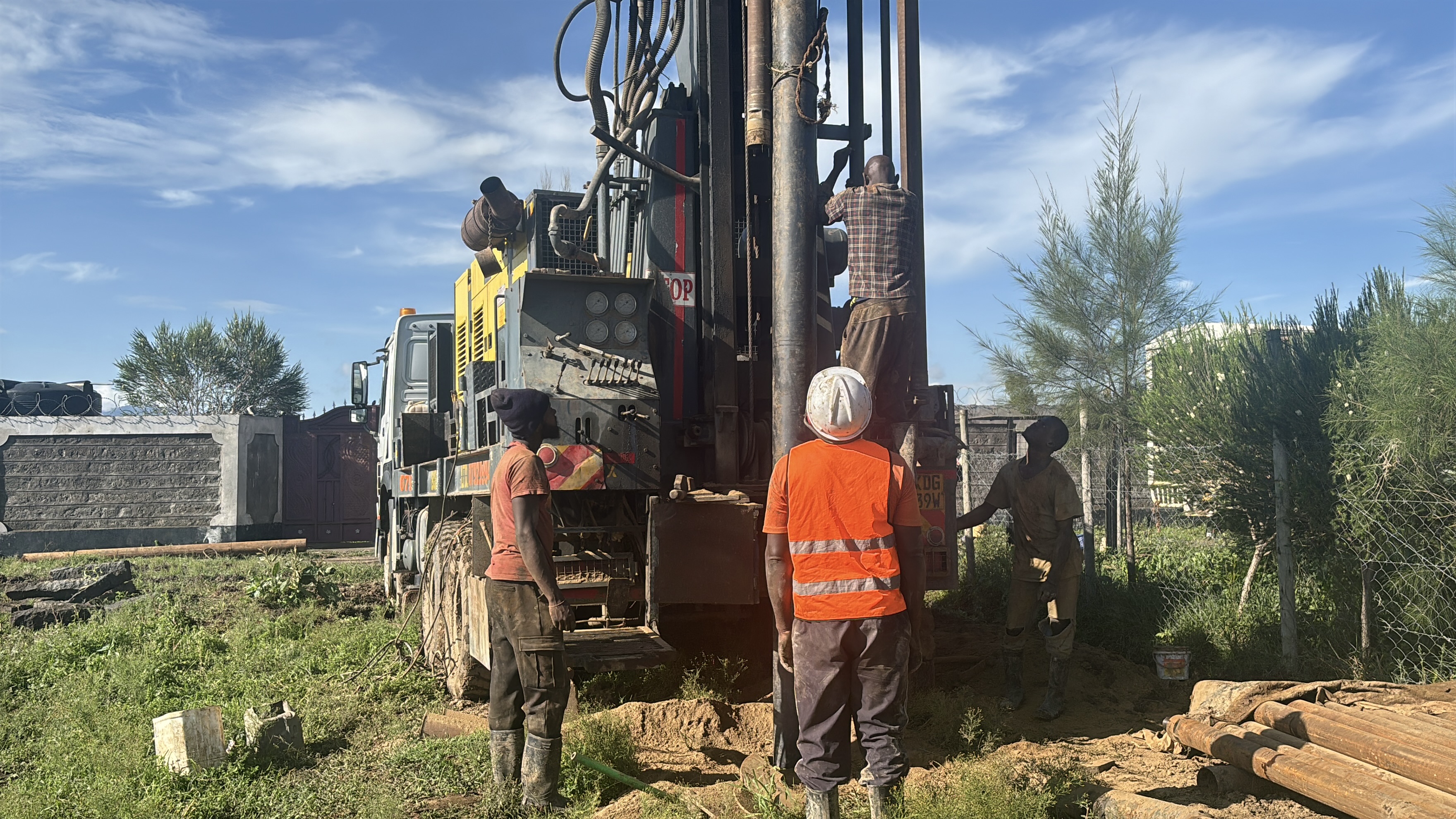
Drilling
Reaching the aquifer — metre by metre
What you will see
- Continuous rig operation during working hours (engine noise is normal)
- Mud or air circulation managing cuttings and borehole stability
- Surface casing installed through unstable upper layers
Your role
- Expect daily progress updates on depth and formations
- Do not add chemicals or waste near the drill site
- Billing is on metres actually drilled — ask for the daily depth log
Drilling is the core phase: rotary mud or DTH (down-the-hole hammer) methods break through soil and rock until we intersect the target aquifer indicated in your survey. We drill at 8 inches diameter — the industry standard for domestic and light commercial supply in Kenya.
Drillers watch cuttings every metre to spot water-bearing zones. 8-inch surface casing stabilizes the upper section and blocks contaminated shallow water. Depth is guided by geology, not guesswork — typically 60–300 metres depending on county and aquifer.
- Rotary mud drillingSoft to semi-consolidated formations; bentonite slurry stabilizes walls.
- DTH hammer drillingHard rock — high-pressure air breaks and flushes cuttings efficiently.
- Formation loggingEvery metre recorded — you know when water zones are hit.
Client takeaway: You pay for metres actually drilled at the agreed rate (e.g. KES 3,800/m for drilling). Insist on a daily depth log signed by the site supervisor.

Watch: Drilling operations
Rotary drilling to reach groundwater — the heart of your water project.
Flushing
Cleaning the hole before permanent casing
What you will see
- Compressor running — air or water surging up the hole
- Muddy discharge gradually clearing at the surface
- Crew monitoring until cuttings stop and flow stabilizes
Your role
- Keep the discharge area clear — avoid walking in cuttings
- Do not assume “drilling finished” until flushing is complete
- Ask for confirmation before casing is ordered to depth
What you will see
- Compressor running — loud air blast at the borehole mouth
- Muddy or silty water discharging until it runs clearer
- Crew monitoring discharge colour and cuttings
Your role
- Keep the discharge area clear — water may flow across site
- Do not assume “drilling finished” means “ready for pump” — flushing and casing still follow
What you will see
- Compressor running — air or water surging up the hole
- Muddy discharge gradually clearing at the surface
- Crew monitoring until returns are clean enough for casing
Your role
- Allow space for discharge water to drain away safely
- Do not assume “drilling finished” means “ready for pump” — flushing and casing still follow
After drilling, the borehole contains cuttings, drilling mud, and fine particles. Flushing removes this debris using compressed air or clean water circulation so the cavity is stable and ready for casing — we do not rush this step; clear discharge means the hole is truly clean.
Benefits: prevents blockage of screen slots, improves initial water clarity, and reduces risk of collapse before the casing string is lowered.
Client takeaway: Skipping or shortening flushing is a common reason for sand in water and low yield later. Reputable drillers include this in the programme, not as an optional extra.
- Air flushingHigh-capacity compressor blows cuttings from bottom to top.
- Water flush finishFinal pass with clean water to avoid chemical residue.
- Blow testPreliminary check for free water movement in the formation.
Client takeaway: Skipping or rushing flushing leads to sand pumping and blocked screens later — legitimate drillers never go straight to casing on a dirty hole.
Watch: Flushing the borehole
Removing drilling debris before casing installation.
Casing installation
Lining and protecting your borehole for decades
What you will see
- Casing pipes lifted and lowered with the rig
- Threaded or welded joints made watertight
- Slotted sections aligned to water zones from the drill log
Your role
- Confirm casing type (PVC vs steel) matches your signed quote
- Request a simple casing diagram showing depths of plain vs slotted pipe
- Photograph headworks before backfilling for your records
What you will see
- Casing pipes lifted and lowered with the rig
- Threaded or welded joints checked for alignment
- Plain pipe above water zone; slotted screen in aquifer intervals
Your role
- Confirm casing type (PVC vs steel) matches your signed quote
- Ask for a simple casing diagram showing screen depth vs total depth
What you will see
- Casing pipes lowered joint by joint into the borehole
- Plain pipe in upper zones, slotted screen in water layers
- Cement grout placed at the top to seal the annulus
Your role
- Confirm casing type (PVC vs steel) matches your signed quote
- Ask where screen sections sit relative to the survey’s target aquifer
Casing is the permanent pipe inside the borehole. It stops walls from collapsing, keeps polluted surface water out, and guides water from the aquifer to your pump. We install 6-inch production casing as standard — compatible with most submersible pumps and gravel packing practice.
PVC (uPVC) suits many depths and resists corrosion in saline zones. Steel casing is recommended beyond ~150 m, in heavy mud drilling, or where boulders and aggressive rock demand extra strength. Slotted sections are placed exactly in water-bearing zones identified during drilling and survey.
PVC vs steel casing — quick comparison
| Factor | PVC | Steel |
|---|---|---|
| Typical use | Shallow–medium depth, stable geology | Deep holes, hard rock, heavy mud |
| Corrosion | Excellent in many waters | May need protection in saline zones |
| Cost per metre | Lower (e.g. KES 2,000/m) | Higher (e.g. KES 2,400/m) |
| Strength | Good to moderate depths | Superior in difficult formations |
- Plain casingSeals off dry or unstable zones above the aquifer.
- Slotted screenAllows filtered groundwater into the borehole.
- CentralizersKeep casing centred for even gravel placement.
PVC vs steel casing — quick guide
PVC (uPVC)
- Corrosion-resistant — good in many counties
- Lighter — faster to handle on site
- Typical to ~150 m in stable geology
Steel
- Stronger in deep or collapsing holes
- Recommended beyond ~150 m or in boulder zones
- Higher material cost per metre
Watch: Casing installation
Lowering and joining casing joints for a straight, sealed borehole structure.
Gravel packing
Natural filtration around the screen
What you will see
- Washed gravel delivered in bags or bulk
- Gravel poured down the annulus while depth is measured
- Crew verifying coverage around every screen metre
Your role
- Confirm gravel is included in your contract (not an extra surprise)
- Ask how many bags or tonnes were used — it should match screen length
- Report any sudden sand in water after equipping — may indicate poor packing
What you will see
- Washed gravel poured down the annulus around the screen
- Depth measurements to confirm even pack height
- Top seal and headworks preparation beginning
Your role
- Confirm gravel packing is listed in your contract — not assumed
- Report any sand in water after equipping — may indicate poor packing
Gravel is poured into the gap between the borehole wall and the casing (the annulus), especially around slotted sections. Graded 2–4 mm or 4–6 mm washed silica gravel acts as a filter — it stops sand from entering while letting water flow freely. This protects your pump impeller and improves yield.
We add gravel gradually, measuring depth to ensure even coverage around every screen metre. Poor or skipped gravel packing is a common cause of sand pumping and early pump failure.
Client takeaway: Gravel pack is billed per metre in transparent quotes (e.g. KES 300/m). It is not optional on a production borehole with a screen.
Watch: Gravel packing
Placing graded gravel around the screen for filtration and stability.
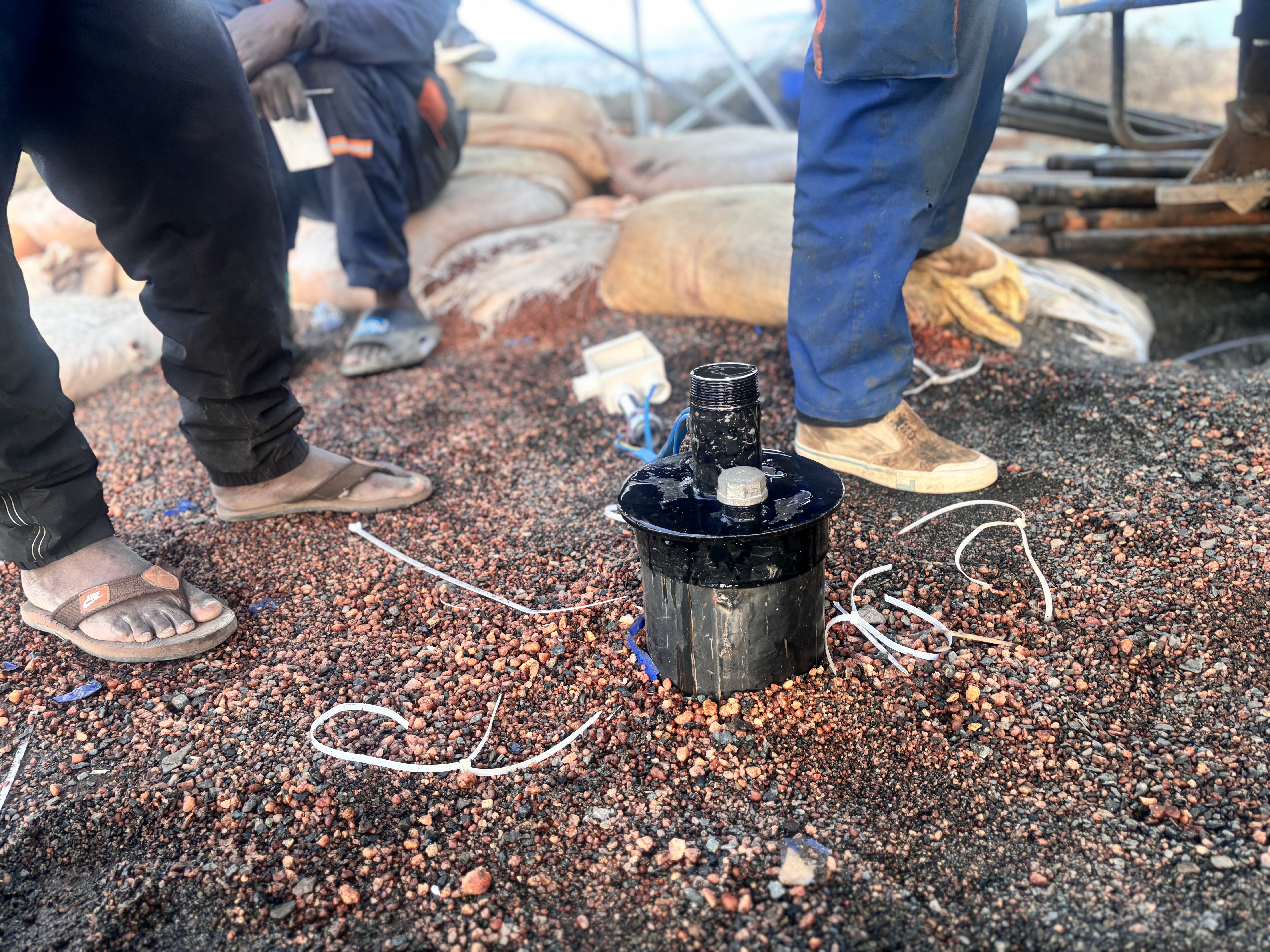
Development & test pumping
Proving yield, quality, and handover
What you will see
- Air lifting or surging to remove fines from the gravel pack
- Test pump running for hours with drawdown measurements
- Water samples taken for basic field checks (lab optional)
Your role
- Review the test-pumping report before pump sizing
- Plan equipping (pump, tank, power) based on certified yield
- Keep the headworks area clear for final cap and apron
Development cleans and “opens” the aquifer after construction. We agitate the formation with compressed air or controlled pumping so fine particles migrate out and flow stabilizes. This step directly affects how much water you get and how clear it stays.
Test pumping (often 24–72 hours) measures sustainable yield in m³/hour or litres per second, records drawdown recovery, and supports your pump selection. Kisima provides documentation you can use for equipping quotes, bank loans, or community water projects.
After development, the borehole head is sealed with a sanitary cap and concrete apron so surface runoff cannot enter. You are then ready for pump installation — electric, solar, or manual depending on depth and yield.
- Borehole developmentAir lift / surging until discharge runs clear.
- Constant-rate testProve yield at a stable pumping rate.
- Recovery monitoringConfirm the aquifer rebounds after shutdown.
- Handover packDepth log, casing diagram, and yield summary.
Client takeaway: Never size a pump before test pumping. Sustainable yield (m³/h or L/s) and drawdown recovery determine the correct pump and power supply.
How we measure a job done properly
Professional drilling is verifiable. These are the checkpoints Kisima documents before handover.
Survey alignment
Drilled within tolerance of GPS coordinates from your hydrogeological report.
Depth log
Metre-by-metre record of formations and water strikes shared with you.
Clean hole
Flushing and development until discharge runs clear — not assumed.
Test pump data
Constant-rate test with drawdown and recovery for pump sizing.
Sanitary seal
Cap and apron prevent surface contamination at the headworks.
Compliance ready
Documentation supports WRA, county, and equipping contractor requirements.
What happens after the rig leaves
Drilling completes the hole — your water system is finished with equipping, storage, and treatment if needed.
Frequently asked by clients
How long does the full drilling programme take?
Will drilling damage my neighbour’s borehole?
Why do you bill per metre drilled?
When can I install the pump?
What if no water is found?
Is drilling noisy? Can we stay on the property?
What documents should I receive at handover?
Ready to start your borehole project?
Talk to Kisima for survey-led drilling, transparent per-metre quotes, and full equipping — from rig mobilization to test pumping and pump installation.